

Application and Product Monitoring & Selection for Data Center Busbar Distribution Systems
Release Date:
2025-01-13
[Abstract] This paper compares the characteristics, advantages, and disadvantages of data center power supply and distribution systems with those of busbar distribution systems, analyzing them from the perspectives of system configuration, scalability, energy efficiency, and other factors. Based on real-world case studies, the paper demonstrates the technical feasibility and economic practicality of busbar distribution systems.
[Keywords] Busbar: Data Center; Power Supply and Distribution; Busway
Introduction
Current Cloud computing 、 Big Data , The rapid advancement of technology in the field of artificial intelligence is ushering in a new approach to power supply and distribution in China’s data centers.
- Traditional Distribution Scheme
As shown in Figure 1, the conventional power distribution scheme for data centers typically involves two 10 kV utility feeders connected to the building’s main distribution room. After passing through transformers and low-voltage switchgear, the dual-circuit utility feeds are routed into a dual-power transfer switchgear located in the data center. From there, cables are run to the UPS equipment, which is then connected via a UPS output cabinet to the row-end distribution cabinets for each rack. Finally, cables from the row-end cabinets are routed to the PDU units inside the racks. This traditional distribution approach is well-established and reliable, with a low single-point failure rate. However, it suffers from several drawbacks: row-end distribution cabinets occupy valuable rack space, cable transmission losses are significant, installation is complex, and scalability and flexibility are limited.
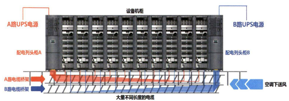
Figure 1: Traditional Cabinet Power Distribution Method
- Intelligent Busbar Distribution Solution
The intelligent busbar distribution system is a data center end-distribution solution that replaces traditional cable-based systems. It comprises a feeder module, functional modules, a terminal busbar trunk, trunk connection modules, tap-off distribution modules, trunk protection modules, and trunk-end terminations. The system features external wiring on the module periphery, circuit protection and switching control, surge protection, monitoring of trunk electrical parameters, status monitoring of protection and control modules, and serves as the primary carrier of electrical energy to facilitate power transmission. As shown in Figures 2 and 3.
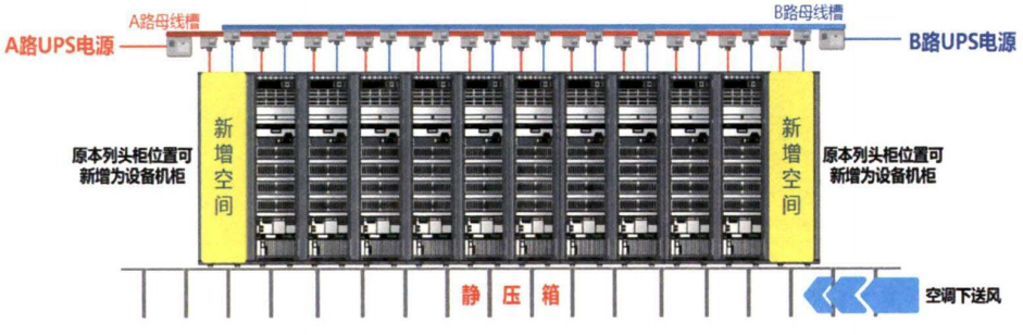
Figure 2: Intelligent Busbar Distribution Method
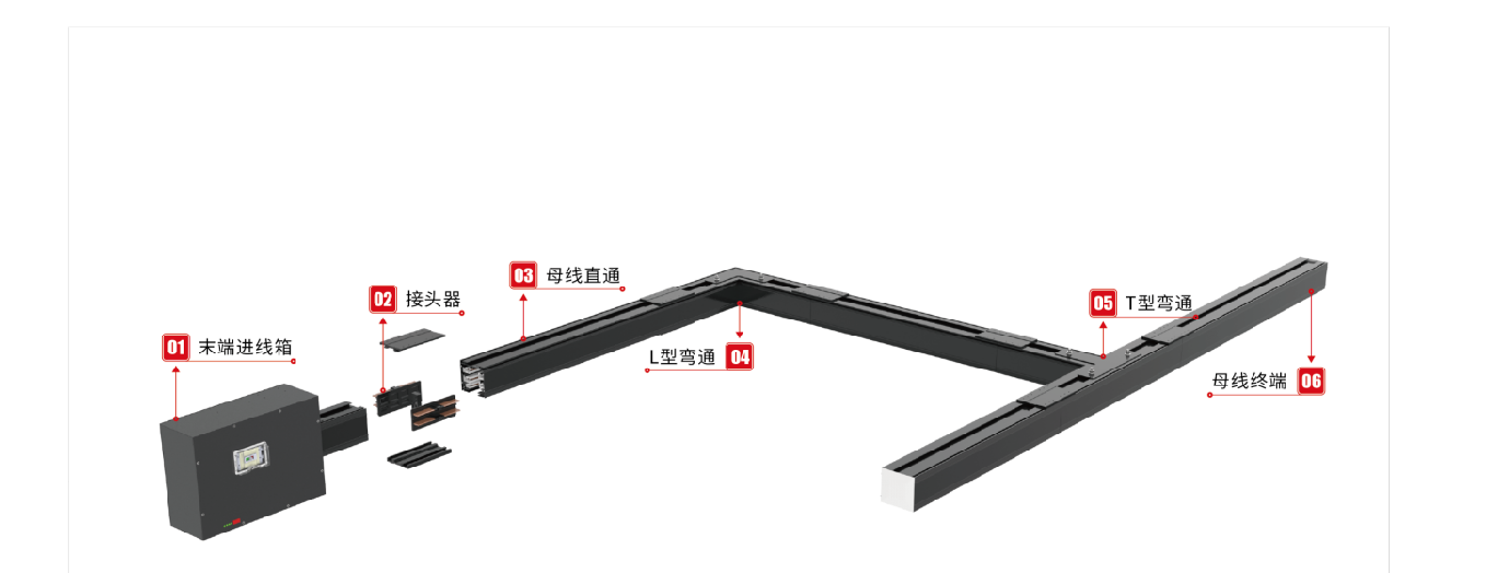
Figure 3: Component Parts of the Intelligent Busbar
(1) Front-end Module: This module is responsible for connecting the UPS distribution cabinet to the busbar, and includes a cable inlet module, molded-case circuit breakers, and a 600 mm straight section of busbar. Within the front-end module, cables pass through the molded-case circuit breakers before being connected to the corresponding busbar terminal blocks. By providing external wiring, circuit protection, and on/off control functions, this module is available in ratings such as 160 A, 250 A, 320 A, 400 A, 500 A, 630 A, and 800 A.
(2) Functional Modules: Integrated functions such as surge protection, monitoring of trunk-line electrical parameters, and status monitoring of the protection control module.
(3) Terminal busbar trunk: the main component for carrying electrical energy and facilitating its transmission. Its basic internal configuration consists of either four copper busbars (L1, L2, L3, N) or five copper busbars (L1, L2, L3, N, PE), with ratings including 160 A, 250 A, 320 A, 400 A, 500 A, 630 A, and 800 A, among others.
(4) Trunk connections: include connectors that enable trunk expansion and various elbows used to change the busbar routing, among others.
(5) Tap-off distribution module: features dual-contact power tapping and utilizes miniature circuit breakers as protective devices. It is a compact distribution module that is plugged directly into the busbar trunking system, providing power to each individual electrical load with current ratings ranging from 6 to 100 A.
(6) Main Line Protection Module: The protective cover plate enhances the protection rating of the main line and effectively prevents personnel from coming into contact with live conductors.
(7) Trunk-end sealing: A seal cap that protects the end of the trunk line, enhancing the protection rating.
(8) The power distribution scheme is as follows: Cables are routed from the front-end UPS distribution cabinet to the busbar trunking system’s inlet module, where power is transmitted via the busbar trunking. Subsequently, distribution modules of appropriate specifications are selected based on the power density of each rack and connected to the rack-mounted PDUs, thereby completing the power distribution for that rack.
- Comparison of Two Distribution Methods
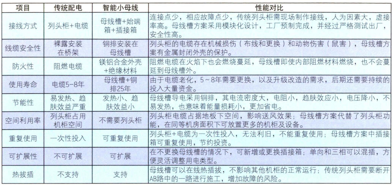
A comparison of the bus-tie cabinet plus cable distribution system and the intelligent micro-busbar distribution system is shown in Table 1.
Table 1: Comparative Analysis of Traditional Column-Mounted Distribution Cabinets and Intelligent Mini Busbars
- Introduction to a Data Center Power Distribution Scheme
This project is subject to the relevant requirements of Clause 4.3.8 of a certain data standard.
The equipment room is planned to accommodate eight rows of equipment, organized into four enclosed cold aisles. No dedicated power distribution rack panels are provided; instead, dual busbars are horizontally installed above the rear doors of each cabinet row. Each individual busbar is fed from a different UPS output circuit to supply power to the A and B feeds for that row. In this design, single busbar trunking sections are fabricated in three standard lengths—2.4 m, 1.8 m, and 1.2 m—and are assembled with 815-mm-long end modules (comprising an 215-mm incoming feeder box and a 600-mm busbar trunking section). The design principle for busbar length prioritizes splicing multiple 2.4-m sections, reserving 1.8-m or 1.2-m sections only for any remaining capacity.
The length of a single-row busbar trunking system shall not exceed the total length of the cabinets in that row. In this data center, each row consists of 12 meters of cabinets, so the busbar trunking length is calculated as 0.815 + 2.4 × 4 + 1.2 = 11.615 meters. With 16 cabinets per row and a power rating of 4 kW per cabinet, the total power for a single row is 64 kW. Therefore, a 160 A busbar trunking system paired with a 160 A main distribution module is selected. Since the cabinet equipment in this project is designed for single-phase power supply, a single-phase plug-in distribution box is chosen, specifically a 32 A unit. Based on the configuration of 16 cabinets, six such boxes are required (one box for every three power distribution modules). By adopting an intelligent mini-busbar distribution scheme, one distribution panel space per row can be eliminated, thereby freeing up additional capacity to accommodate future IT equipment expansion.
Power distribution is implemented via plug-in distribution cabinets that support hot-swapping, enabling on-demand scaling of power requirements at any time without requiring major infrastructure modifications. Moreover, single-phase to three-phase conversion can be achieved on the same busbar trunking system without disrupting other operating cabinet equipment. It is precisely because of these advantages that, with the rapid expansion of large-scale data center facilities,
- Concluding Remarks
In recent years, intelligent micro-busbar distribution solutions have not yet achieved widespread adoption and application. However, this aligns with the strategic goals of peaking carbon emissions and achieving carbon neutrality as outlined in the national 14th Five-Year Plan for large-scale IDC data centers. It is anticipated that, in the near future, intelligent micro-busbar distribution will be deployed on a large scale and, as design continues to evolve and improve, will become a mainstream solution.
References
[1] He Xin. “Application of a Small Busbar Distribution System in a Data Center”
[2] China Academy of Electronic Engineering Design. GB 50174-2017 Code for Design of Data Centers [S]. Beijing: China Planning Press, 2017.
【3】Acrel EMS -IDC Data Center Comprehensive Energy Efficiency Management Solution - Sample
[4] Data Center Solutions Sample, Version 2022.04
Data center,Busbar,Intelligent Busbar,Small busbar
Related News
Exploring the Future Development and Applications of Busbar Trunking Systems
This article explains the importance of busbar trunking systems in modern power systems and their future development trends.
2026-04-10

Hello, how may we assist you?
*Note: Please ensure all information is accurate; we will contact you as soon as possible.
SAF Coolest v1.3.1.1 设置面板 JYOSD-ZUEU-XXZSE-SZV
无数据提示
Sorry, this section is currently being updated. Please stay tuned!
You can view other sections or return.Home