

A Brief Discussion on the Design of Power Supply and Distribution Systems for Data Center Server Rooms
Release Date:
2025-02-13
A Brief Discussion on the Design of Power Supply and Distribution Systems for Data Center Server Rooms
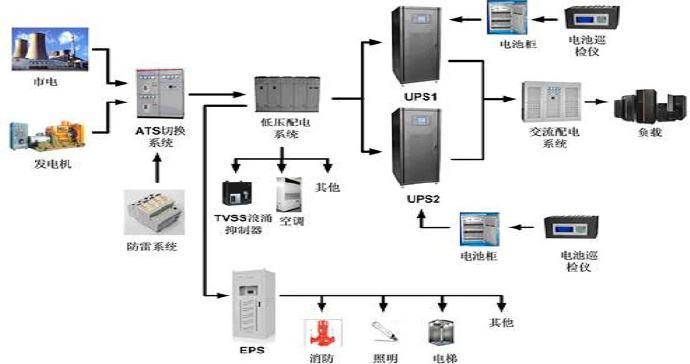
Modern data centers house a large number of computers, and the power supply for such facilities is required to Power Supply and Distribution The system must remain functional at all times, which sets it apart from typical buildings. Power Supply and Distribution System , it is a complex, integrated system that encompasses mains power supply, lightning protection and grounding, electrostatic discharge protection, UPS uninterruptible power supply, and diesel generators. Motor Moreover, each system is interwoven and mutually influential, which necessitates that we take multiple factors into account during the design process.
I. System Overview
Modern data center facilities house a large number of computers, and their power supply systems are required to operate continuously, be easily scalable, simple to maintain, highly fault-tolerant, and—most importantly—cost-effective. As the foundational infrastructure for modern informationization, data centers provide a stable and secure operating environment for all business operations; and the data center’s power supply and distribution system serves as the heart and main arteries of this infrastructure. The reliability of the power supply and distribution system is critical to ensuring the proper functioning of other subsystems and the uninterrupted operation of core business processes. Unlike the power supply and distribution systems in ordinary buildings, the data center system is a highly integrated, interdependent network that encompasses grid power, lightning protection and grounding, electrostatic discharge control, UPS uninterruptible power supplies, diesel generators, and more. These subsystems are closely interconnected and mutually influence one another, which necessitates that designers take a wide range of factors into account during the design phase.
II. Design Standards
Data centers have dedicated design standards; the world’s first comprehensive telecommunications infrastructure standard for data centers, TIA-942 “Telecommunications Infrastructure Standard for Data Centers,” was approved in April 2005 by the Telecommunications Industry Association (TIA), the TIA Technical Engineering Committee (TR42), and the American National Standards Institute (ANSI). Domestic codes and standards are also developed by integrating international standards with the specific conditions of China’s data center construction and development. The national design code for data centers, GB 50174—2008, “…” Design Code for Electronic Information System Computer Rooms It was also promulgated on November 12, 2008, and came into effect on June 1, 2009.
The design of a data center begins with determining the facility’s classification based on the criticality of its users and the owner’s specific requirements for reliability, security, and other performance criteria. The appropriate power supply and distribution system is then selected in accordance with the designated classification. In China, data centers must first comply with national codes and standards. According to GB 50174—2008, which governs the classification of data centers, electronic information system rooms are categorized into three levels: A, B, and C. During the design phase, the appropriate classification should be determined by considering the room’s intended use, operational management requirements, and its significance in the economic and social contexts.
III. Design Principles
The design of data center power supply and distribution systems shall comply with, or be designed in accordance with, relevant national and industry standards and codes, and may also reference applicable international standards and codes. In light of the high power density and stringent reliability requirements typical of data centers, appropriate technical measures shall be adopted. At the same time, the design must meet the enterprise standards and specifications established by the project owner.
The design of data center power supply and distribution systems shall adhere to the principles of zoning and hierarchical structuring. Within each functional zone, the power supply reliability for all equipment must ensure that all devices operate in accordance with the zone’s specified standards, while minimizing the impact area of any localized faults in the power supply and distribution system.
Data centers feature high power density and substantial total power consumption; therefore, the design of their power supply and distribution systems should fully leverage mature and effective energy-saving measures to minimize system losses.
IV. Requirements Analysis for the Data Center Server Room Power Supply and Distribution System
With the rapid advancement of information technology and the widespread adoption of the Internet, the application of information systems across all sectors of society has expanded dramatically, leading to an exponential increase in the volume of information and data. Consequently, the demand for data centers has grown steadily, while the requirements placed on them have become increasingly stringent: information equipment is becoming more powerful and its power density is rising. The electrical load per server rack in data centers has increased from the previous 2 kVA per rack to 3 kVA per rack, 4 kVA per rack, and even higher. Similarly, the average electrical load per unit area of the server room has risen from 1 kVA per square meter to 1.5 kVA per square meter, 2 kVA per square meter, and beyond.
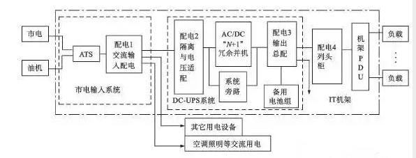
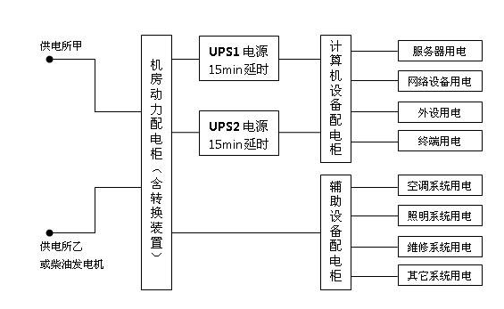
The statistical analysis of data center power loads should be conducted at two levels: the UPS power supply system load (output) and the utility power supply system load. The utility power supply system load (output) primarily includes the UPS power supply system (input), the precision air-conditioning system in the equipment room, the equipment-room lighting, and building electrical equipment. The UPS power supply system load (input) equals the supply load plus the charging load. The precision air-conditioning system load in the equipment room is calculated as the rated capacity of each primary air-conditioning unit multiplied by its load factor, with the number of units denoted by N. The UPS power supply system load (output) mainly comprises computing equipment, servers, storage systems, network equipment, and minicomputers; when the specific load devices are clearly identified, the load is tallied based on device-specific data; when the specific load devices are not clearly defined, the load is estimated based on the average load per equipment cabinet. If the number of equipment cabinets is also uncertain, the load may be estimated on the basis of the average load per unit area of the equipment room.
V. Power Supply and Distribution System Design for Data Center Server Rooms
- Arrangement of the Power Supply and Distribution System
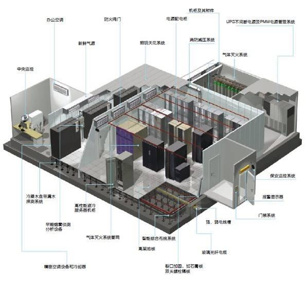
The main equipment in the data center’s power supply and distribution system includes: UPS, batteries, Distribution cabinet such as diesel generators. These units have large footprint and heavy weight; therefore, their placement must take into account functional requirements, spatial and load-bearing constraints, and potential environmental hazards.
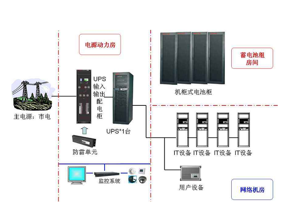
The power supply system for data center server rooms shall include a dedicated distribution room and a substation. The UPS power room should be located close to the equipment room (the load center) to minimize voltage drop and power losses between the UPS output and the connected loads. Whether the UPS host, distribution cabinets, and battery banks need to be physically separated shall be determined in accordance with the data center’s tier requirements. In addition, given that UPS systems are large, heavy, and relatively noisy, they must be installed in a location with adequate structural load-bearing capacity that does not compromise the office or rest environment. When selecting the location of the distribution cabinets, functional requirements should be the primary consideration; the cabinets should be positioned as close as possible to the power loads while still complying with the overall functional zoning. The generator room is preferably located on the ground floor; if it is situated in the basement, special attention must be paid to ensuring that the air intake and exhaust ducts meet the required specifications, and to compliance with fire safety regulations for the fuel storage facilities of the generator set, including the daily-use fuel tank and the main fuel storage tank.
Substations, generator rooms, and UPS power rooms shall all be provided with sufficient floor space to accommodate future expansion in tandem with the equipment rooms, thereby meeting increased power supply demands resulting from expanded equipment room footprints or higher equipment power densities. For buildings not specifically designed for data centers, it is essential to verify that they comply with the requirements for equipment installation and cabling, including floor load capacity, clear ceiling height, seismic design category, and fire-resistance rating.
- Power Supply and Distribution System Design
1. Design of the Mains Power Distribution System
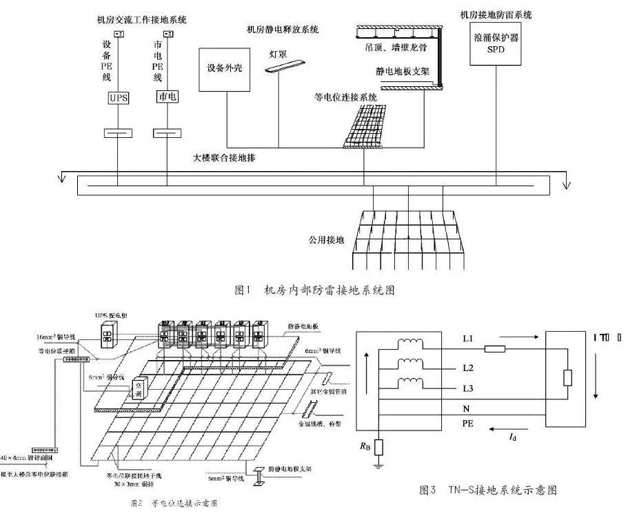
Mains power distribution is primarily used to supply precision air-conditioning equipment in the equipment room, general lighting, and ventilation and exhaust systems, as well as maintenance operations. socket , general power supplies, UPS equipment, etc. The mains-powered distribution system is typically supplied by the building’s main distribution cabinet and operates on 50 Hz AC at 380/220 V. Three-phase five-wire Power supply: TN-S grounding system, with separate neutral and protective earth conductors and a voltage between the neutral and earth conductors of less than 1 V.
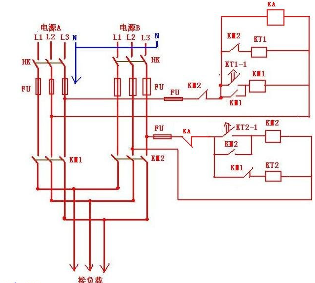
For data centers with general reliability requirements, it is advisable to provide dual mains power feeds; where site constraints apply, a single mains power feed may be acceptable. When two mains power feeds are provided, they should be configured in a redundant arrangement, and may also serve as a capacity expansion path for future power supply needs.
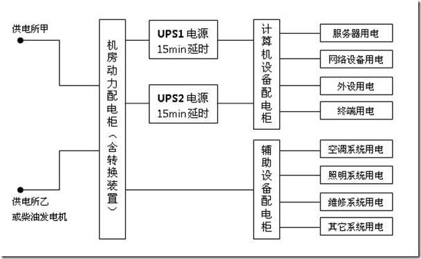
The supply capacity of each utility power feed shall be sufficient to meet the demand of all Class I and Class II loads, including the UPS power system, precision data center air conditioning, data center lighting, battery charging, and Class I and Class II loads in building services. The combined supply capacity of the two utility power feeds shall provide full redundancy; under normal conditions, both feeds shall operate simultaneously, with automatic transfer at the load equipment input terminals.
Mains-powered power distribution cabinets typically employ a radial distribution scheme, with power supplied directly to each electrical load or distribution box. All power distribution cables within the equipment room must be properly designed. Cable tray Alternatively, steel conduit may be used for wiring. The mains power distribution cabinet is equipped with fire-alarm interlock protection; in the event of a fire, it can automatically interface with the fire-fighting system to promptly disconnect the power supply. Inside the power distribution cabinet and lighting distribution box, Switch Effective lightning protection measures shall be provided for the main components.
2. Design of Self-Provided Emergency Power Supply System
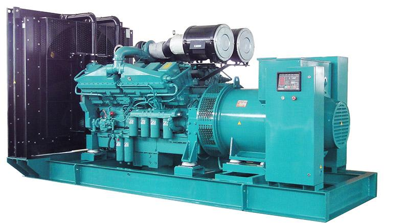
Data centers generally adopt Diesel generator set As a self-provided emergency power source, large-scale, high-grade data centers can also opt for high-power units that offer high reliability, excellent output power quality, strong capability to handle nonlinear loads, compact size, and light weight. Gas Turbine Generator Set Data centers with general reliability requirements should be equipped with a single dedicated emergency power supply, the capacity of which shall be sufficient to meet the full load demands of all Class I and Class II loads, including the UPS system, data center air conditioning, data center lighting, battery charging, and Class I and Class II loads in building services. When site conditions are constrained and the utility power supply is highly reliable, mobile generator sets may be used, either partially or entirely, as the dedicated emergency power source. The fuel reserve for the generator set shall be determined on the basis of the data center’s classification, taking into account the reliability of the utility power supply, the reliability of fuel delivery, and fire safety requirements; in general, the reserve should not be less than the amount of fuel required for the generator set to operate at full load for 8 hours.
3. UPS Power Supply and Distribution System Design
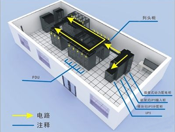
UPS power distribution is primarily used for computer equipment, servers, minicomputers, storage systems, network devices, and security surveillance equipment. UPS power systems typically employ a three-level distribution architecture: system output distribution cabinet → data center distribution cabinet → rack-mounted power distribution unit.
There are two methods for calculating the capacity of a UPS power system’s battery pack:
(1) Calculated based on load current;
(2) Calculated based on load power;
The result of calculation based on load current is the total capacity of the battery bank, from which the capacity of a single battery unit and the number of units are then determined. The result of calculation based on load power is the number of battery units required for the selected capacity rating. The results obtained from these two methods can be cross-checked against each other.
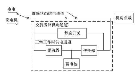
For single-power-input equipment, even when a dual-unit redundant UPS power system is employed, it is advisable to connect such equipment to only one of the units. In a dual-unit redundant UPS system, a portion of the capacity in each unit can be regarded as providing parallel redundancy. For single-power-input equipment that requires dual-circuit power supply, a static transfer switch (STS) should be installed at its input. The performance of the STS must meet the relevant requirements, with a typical transfer time of less than 5–10 ms.
When the load equipment has stringent requirements for the neutral-to-ground voltage, isolation can be implemented in the data center’s distribution cabinet. Transformer Sometimes, to ensure high-quality power output after the UPS is bypassed due to a fault, an isolation transformer is installed at the UPS bypass output.
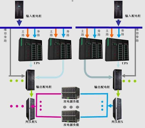
Data center UPS power supply and distribution systems typically employ redundant power configurations, with standalone units being rarely used. Redundant power supply ensures that, in the event of a failure in one UPS unit, the power requirements of critical equipment in the data center can still be met—something that is not achievable with a single-unit configuration. From the perspective of redundant configuration schemes, the following approaches are commonly used:
(1) Hot-standby redundant UPS power supply mode
The primary UPS is loaded, while the standby UPS operates either unloaded or with non-critical loads, and the standby UPS is connected to the bypass input of the primary UPS. This configuration offers considerable flexibility: it does not require the two UPS units to be from the same manufacturer, nor does it necessitate additional auxiliary circuits, thereby avoiding any increase in procurement costs. However, if the primary UPS fails, the standby UPS must take over the entire load; consequently, the design must accurately calculate the total load that the standby UPS will need to handle in the event of a primary UPS failure. A drawback of this approach is that the standby UPS must have the capability to handle step-load changes, and it does not allow for expansion of the power system. Moreover, when two UPS units of different capacities are paralleled, the system can only deliver power at the output capacity of the smaller unit.
(2) Direct Parallel Redundant UPS Power Supply Mode
To overcome the limitations of hot-backup redundant power-supply systems, advances in UPS control technology now enable UPS units with identical rated output power to be directly paralleled to form a redundant power-supply configuration. To ensure high-quality parallel operation, it is essential that all units maintain the same frequency and phase, and that load is evenly distributed among them. This power-supply approach offers strong instantaneous overload capability, automatic power-sharing, mutual backup between units, enhanced power-supply reliability, and convenient system expansion. However, it also gives rise to circulating currents, which increase reactive-power losses and reduce system reliability; additional auxiliary circuits are required, leading to higher costs and more potential failure points. In design, when two units are configured for mutual redundancy, each should be sized for 50% of the total load. Moreover, the more units that are paralleled, the lower the load-carrying capacity of each individual unit.
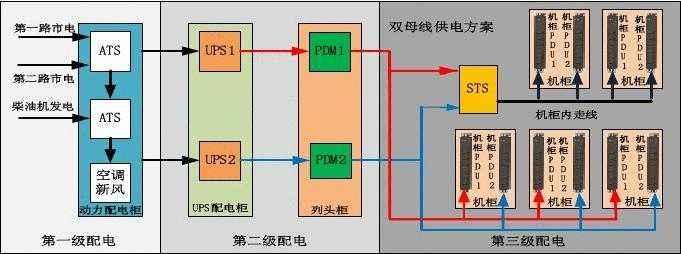
(3) Dual-bus redundant power supply method
The dual-bus power supply configuration employs two independent bus lines to power backend equipment, with each bus equipped with an identical UPS power-supply system. This approach eliminates the potential “single-point bottleneck” failure risk that could arise between the UPS output and the end-user load, thereby enhancing the fault-tolerant capability of the power-supply system. This configuration supports online maintenance, online capacity expansion, and online upgrades, improving the availability of critical bus lines and meeting the power requirements of dual-power-input equipment, thus truly achieving 24/7/365 operational reliability. However, the dual-bus redundant power-supply scheme effectively entails constructing two complete sets of the aforementioned power-supply circuits, which increases costs by more than double. Meanwhile, to accommodate single-power-input equipment, an Static Transfer Switch (STS) can be installed at the output to ensure reliable power delivery.
- Installation of power supply and distribution equipment and cable laying
The UPS and precision air-conditioning power systems in the computer room shall be supplied via dedicated incoming distribution panels. These panels shall be fed by two independent power sources with automatic transfer switching. The main power supply and the bypass power supply for the UPS host unit shall be separately sourced and preferably routed from different incoming distribution panels. The UPS power system output shall employ a radial, dual-circuit distribution configuration. Furthermore, the UPS power system output shall utilize three-phase distribution with phase-specific termination at the load end to ensure three-phase balance.
The computer room’s power distribution cabinets and UPS power cabinets shall be floor-mounted; the power distribution boxes and lighting distribution boxes shall be flush-mounted on the wall with their bottom edges 1.4 meters above the floor. The bases of the distribution cabinets and other electrical equipment shall be securely anchored to the building floor and properly grounded. Separate maintenance and testing outlets shall be provided within the computer room, clearly distinguished by distinct markings; the testing outlets shall be powered by the UPS, while the maintenance outlets shall be supplied by the mains power. All wiring installations shall be carried out in accordance with the equipment layout and design drawings, with careful consideration given to minimizing supply distances. Within the computer room, power cables, signal cables, and communication cables shall be routed separately and must not share the same cable tray. The outgoing circuits from the UPS power distribution box (cabinet)… Distribution line Galvanized steel conduit shall be installed beneath the raised floor in the equipment room and routed to each row of network or server cabinets, with power supplied to the cabinets via outlets or industrial connectors.
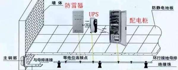
- Reliable grounding
Data centers shall adopt a combined grounding system, in which the ring-shaped grounding electrode surrounding the building, the building’s foundation grounding grid, and the transformer grounding grid are interconnected via copper grounding busbars. Within critical equipment rooms, a combined grounding grid shall be formed using copper braided straps. The metal frames of all distribution cabinets and distribution boxes, as well as their structural steel foundations, must be reliably connected to the protective earth (PE) conductor. The grounding terminals on doors and frames shall be connected by bare copper braided conductors. In lighting distribution boxes, the tripping current of residual-current devices shall not exceed 30 mA, and the tripping time shall not exceed 0.1 s. PE branch conductors must be connected directly to the PE main conductor; series connections are prohibited. The neutral conductor (N pole) at the output of the UPS power cabinet must be connected to the grounding main conductor derived directly from the grounding system for repeated grounding purposes. The resistance of the combined grounding system shall be less than 4 Ω, while that of the separate grounding system shall be less than 1 Ω. When luminaires are installed at a height of less than 2.4 m above the floor, any accessible exposed conductive parts of the luminaires must be reliably connected to the protective earth (PE), with dedicated grounding bolts and clear identification markings. When the external power supply cable enters the equipment room’s power management room, it shall be Cable The metal outer sheath shall be connected to the grounding system. The entire length of the metal cable tray and its supports shall be bonded to the protective earth (PE) main at no fewer than two points, and copper-core jumpers shall be installed across both ends of the connecting plates between cable trays. Ground wire The minimum allowable cross-sectional area of the grounding conductor shall be no less than 6 mm², and protective earth (PE) conductors shall not be connected in series between outlets.
- Data Center Antistatic
Given the significant impact of static electricity on computer equipment, electrostatic protection in data centers is of paramount importance. Currently, the primary electrostatic protection measures involve installing anti-static flooring throughout the data center floor, with adjacent floor panels precisely interconnected via cross beams to form a unified conductive system that is grounded through underfloor copper grounding plates. The flooring substrates are typically made of all-steel, aluminum alloy, or calcium sulfate materials. Wall surfaces are constructed using color-coated steel panels or coated with anti-static paint, while metal suspended ceiling tiles are installed to provide electrostatic shielding and mitigate interference from external strong magnetic fields.
- End-of-Line PDU
As the name suggests, a Power Distribution Unit (PDU) is designed to distribute power and provide additional management functions. Power distribution involves the allocation of current, voltage, and connection interfaces, while power management encompasses switch control—including remote operation—monitoring of various circuit parameters, circuit switching, load limitation, proper matching and installation of power outlets, cable organization, space management, surge protection, and polarity detection. Given that nearly all IT equipment in data centers is already housed—or will soon be housed—in standard server racks, PDUs have become indispensable rack accessories and are receiving increasing attention from all stakeholders. Compared with ordinary power strips, PDUs offer several key advantages: more rational design and layout, stricter quality and compliance standards, longer safe and trouble-free operating life, superior protection against leakage, overvoltage, and overload, enhanced durability under frequent plugging and unplugging, lower heat generation, and more flexible and convenient installation. They are particularly well suited for industries with stringent power requirements and fundamentally eliminate the safety hazards associated with ordinary power strips, such as frequent power outages, component burnout, and fire risks caused by poor contact or insufficient load capacity.
VI. Summary
Data centers serving different purposes or operating at different tiers have varying reliability requirements, which directly impact both capital expenditure and operational costs. The power supply and distribution system is the most critical infrastructure of a data center and should be systematically considered and comprehensively planned from the very outset of its construction. In accordance with the specific reliability requirements of the data center, appropriate technical measures must be implemented in areas such as the selection of power sources, the layout of the power supply and distribution system, and the system’s architecture and configuration. At the same time, proven and effective energy-saving measures should be fully leveraged to minimize losses in the power supply and distribution system. Where a data center comprises functional zones of differing levels, these should be treated differently in the design of the power supply and distribution system to avoid unnecessary capital outlays and operational expenses.
Data center,Small busbar,Intelligent Busbar
Related News
Exploring the Future Development and Applications of Busbar Trunking Systems
This article explains the importance of busbar trunking systems in modern power systems and their future development trends.
2026-04-10

Hello, how may we assist you?
*Note: Please ensure all information is accurate; we will contact you as soon as possible.
SAF Coolest v1.3.1.1 设置面板 JYOSD-ZUEU-XXZSE-SZV
无数据提示
Sorry, this section is currently being updated. Please stay tuned!
You can view other sections or return.Home