

What are the power supply requirements for data center server rooms? How should the power supply and distribution system be configured?
Release Date:
2025-08-05
The power supply and distribution system is the most critical infrastructure of a data center and should be comprehensively considered and thoroughly planned from the very beginning of the data center’s construction. In accordance with the data center’s requirements for power supply reliability, appropriate technical measures must be implemented in areas such as the selection of power sources, the layout of the power supply and distribution system, and the system’s architecture and configuration.
Preface:
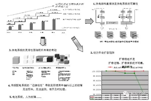
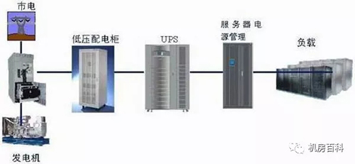
The power supply and distribution system in a data center facility is a highly integrated, interdependent network that encompasses grid power, lightning protection and grounding, electrostatic discharge control, UPS uninterruptible power supplies, diesel generators, and more. Each subsystem is interconnected and mutually influences the others, necessitating comprehensive consideration of multiple factors during system design and layout. As the “heart” and “main arteries” of the facility’s infrastructure, the stability of the power supply and distribution system is critical to ensuring the reliable operation of all other systems and the uninterrupted performance of core business functions. The following section outlines the power requirements for data centers and presents recommended system configuration and layout strategies.
Data Center Power Demand
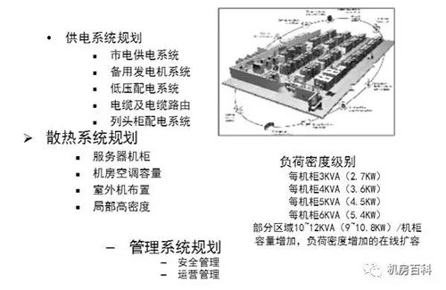
(1) Increased rack density and higher power density lead to an overall increase in power supply capacity. • Individual cabinet load: 2 kW/rack – 3 kW/rack – 4 kW/rack – and higher; • Average load per unit area: 0.5 kVA/m² – 1 kVA/m² – 1.5 kVA/m² – 2 kVA/m² – and higher;
(2) Reliability Requirements—The reliability requirements for power supply and distribution systems are correspondingly increased. • Power supply and distribution system reliability: 99.00%–99.90%–99.99%–99.999%—and higher;
Demand Analysis for the Power Supply and Distribution System of Data Center Server Rooms
As the requirements for data centers continue to rise, information equipment is becoming increasingly powerful and its power density is steadily increasing. The electrical load per equipment rack in data centers has increased from the previous 2 kVA per rack to 3 kVA per rack, 4 kVA per rack, and even higher. Similarly, the average electrical load per unit area of the server room has risen from 1 kVA per square meter to 1.5 kVA per square meter, 2 kVA per square meter, and beyond. Consequently, the statistical analysis of data center power loads should be conducted at two levels: the load of the UPS power supply system (output) and the load of the utility power supply system.
The statistical analysis of the load (output) of the mains power supply system primarily includes: the UPS power supply system (input), the data center precision air-conditioning system, data center lighting, and building electrical equipment. The UPS power supply system load (input) equals the supply load plus the charging load. The data center precision air-conditioning system load is calculated as: the rated capacity of each primary air-conditioning unit multiplied by the load factor, with the total number of units taken into account.
The statistical analysis of the UPS power supply system’s load (output) primarily covers computer equipment, servers, storage systems, network equipment, and minicomputers. When the specific load devices are identified, the statistics are compiled based on device-specific data; when the specific load devices are not clearly defined, the statistics are calculated based on the average load per equipment cabinet. If the number of equipment cabinets is also unknown, the average load can be estimated based on the data center floor area.
Layout of the Power Supply and Distribution System for Data Center Server Rooms
The primary equipment in a data center’s power supply and distribution system includes UPS units, batteries, switchgear cabinets, and diesel generators. These devices are bulky and heavy per unit of floor space, so their placement must balance functional requirements with constraints on available space and structural load-bearing capacity, while also minimizing potential hazards to the external environment. The data center’s power supply system should be housed in a dedicated distribution room and substation, with the UPS power room located as close as possible to the equipment rooms (the load center) to minimize voltage drop and power losses between the UPS output and the connected loads.
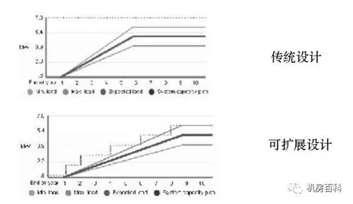
Whether the UPS power host, distribution cabinet, and battery bank should be physically separated depends on the data center’s tier requirements. In addition, given that UPS systems are large, heavy, and relatively noisy, they must be installed in a location with adequate structural load-bearing capacity that does not compromise the office or rest environment. The selection of the distribution cabinet’s location should primarily be guided by functional needs: the cabinet should be positioned as close as possible to the power loads while still adhering to the overall functional zoning. The generator room is preferably located on the ground floor; if it is instead situated in the basement, special attention must be paid to ensuring that the air intake and exhaust ducts meet the required specifications, and to complying with fire safety regulations for the generator set’s fuel storage system (including daily-use fuel tanks and storage tanks). Substations, generator rooms, and UPS power rooms should all be provided with sufficient floor space to accommodate future expansion as the equipment rooms grow, thereby addressing increased power demand resulting from expanded equipment room footprints or higher equipment power densities. For buildings not specifically designed for data centers, it is essential to verify that they meet the requirements for equipment installation and cable routing, including aspects such as floor live load, clear ceiling height, seismic resistance rating, and fire-resistance rating.
Design of the Mains Power Distribution System
Mains power distribution is primarily used to supply precision air-conditioning equipment in the equipment room, general lighting, supply and exhaust ventilation systems, maintenance outlets, general power loads, and UPS equipment. Typically, mains power distribution is provided by a power supply and distribution system fed from the building’s main distribution panel, utilizing 50 Hz AC with a 380/220 V three-phase five-wire power supply and a TN-S earthing system, in which the neutral and protective earth conductors are separately routed and the voltage between them is less than 1 V.
For data centers with general reliability requirements, it is advisable to provide two independent utility power feeds; where site constraints apply, a single utility power feed may be sufficient. When two utility power feeds are provided, they should be configured in a redundant arrangement or as a capacity-expansion scheme. Each feed must be capable of supplying the full load of Class I and Class II equipment, including the UPS system, precision computer-room air-conditioning units, lighting, battery charging, and other Class I and Class II loads within the building services. The combined capacity of the two utility feeds shall provide full redundancy, with both feeds operating simultaneously under normal conditions and automatically switching at the load equipment’s input terminals.
Mains power distribution cabinets typically employ a radial distribution scheme, supplying power directly to individual electrical loads or distribution boxes. All power distribution cables within the equipment room must be routed using cable trays or steel conduit. The mains power distribution cabinet is equipped with fire-alarm interlock protection; in the event of a fire, it can automatically interface with the fire protection system to promptly disconnect the power supply. Switches and key components within the power distribution cabinet and lighting distribution box shall be provided with effective lightning-protection measures.
Design of Standby Emergency Power System
Data centers typically rely on diesel generator sets as their on-site emergency power supply. For large-scale, high-grade data centers, high-reliability, high-quality output, strong capability to handle nonlinear loads, compact footprint, and lightweight high-power gas-turbine generator sets may also be selected. Data centers with standard reliability requirements are generally advised to install a single on-site emergency power feed, with a capacity sufficient to meet the full demand of Class I and Class II loads, including UPS systems, data center air conditioning, data center lighting, battery charging, and other Class I and Class II loads within building services.
When data center conditions are constrained and the grid power supply is highly reliable, mobile generator sets may be used, either in part or in full, as an on-site emergency power source. The fuel reserve for the generator sets shall be determined comprehensively based on the data center’s classification requirements, combined with the reliability of the grid power supply, the reliability of fuel delivery, and fire safety requirements; generally, the reserve should not be less than the amount of fuel required for the generator sets to operate at full load for 8 hours.
UPS Power Supply and Distribution System Design
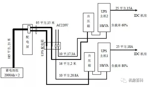
UPS power distribution is primarily used for computer equipment, servers, minicomputers, storage systems, network devices, and security surveillance equipment. UPS power systems typically employ a three-level distribution scheme: system output distribution cabinet → data center distribution cabinet → cabinet-level distribution unit. There are two common methods for calculating the capacity of the battery pack in a UPS power system:
(1) Calculated based on load current;
(2) Calculated based on load power;
The result of calculation based on load current is the total capacity of the battery bank, from which the capacity of a single battery unit and the number of units are then determined. The result of calculation based on load power, on the other hand, indicates the number of battery units required to meet the selected capacity specification. The outcomes of these two calculation methods can be cross-checked against each other. For equipment with a single power input, even when a dual-unit redundant UPS system is employed, it is still advisable to connect such equipment to only one of the units. In a dual-unit redundant UPS system, a portion of the capacity in each unit can be regarded as providing parallel redundancy. For single-input equipment that requires dual-circuit power supply, a static transfer switch (STS) should be installed at its input terminal. The performance of the STS must meet the relevant requirements; typically, the transfer time should be less than 5–10 ms. When the load equipment has stringent requirements for the zero-to-ground voltage, an isolation transformer may be installed in the data center’s distribution cabinet. In some cases, to ensure high-quality power output after the UPS bypass operation in the event of a fault, an isolation transformer is often installed at the UPS bypass output.
Data center UPS power supply and distribution systems typically employ redundant power configurations, with standalone units being rarely used. Redundant power supply ensures that, in the event of a failure in one UPS unit, the power requirements of critical equipment in the data center can still be met—something that is not achievable with a single-unit configuration. From the perspective of redundant configuration schemes, the following approaches are commonly used:
Hot-standby redundant UPS power supply mode
The primary UPS carries the full load, while the standby UPS operates either at no load or with non-critical loads, and its BYPASS input is connected to the primary UPS. This configuration offers considerable flexibility: it does not require the two UPS units to be of the same brand, nor does it necessitate additional auxiliary circuits, thereby avoiding any increase in procurement costs. However, if the primary UPS fails, the standby UPS must take over the entire load; consequently, the design must accurately calculate the total load that the standby UPS will need to handle in the event of a primary UPS failure. A drawback of this approach is that the standby UPS must have the capability to handle step-load changes, and it does not allow for expansion of the power system. Moreover, when two UPS units of different capacities are paralleled, the system can only deliver power at the capacity of the smaller unit.
Direct Parallel Redundant UPS Power Supply Configuration
To overcome the limitations of hot-backup redundant power-supply systems, advances in UPS control technology now enable UPS units with identical rated output power to be directly paralleled to form a redundant power-supply configuration. To ensure high-quality parallel operation, it is essential that all units maintain the same frequency and phase, and that load is evenly distributed among them. This power-supply approach offers strong instantaneous overload capability, automatic power-sharing, mutual backup between units, enhanced power-supply reliability, and convenient system expansion. However, it also gives rise to circulating currents, which increase reactive-power losses and reduce system reliability; additional auxiliary circuits are required, leading to higher costs and more potential failure points. In the design phase, for example, when two units are configured for mutual redundancy, each should be sized to handle only 50% of the total load. As the number of paralleled units increases, the load-carrying capacity of each individual unit decreases accordingly.
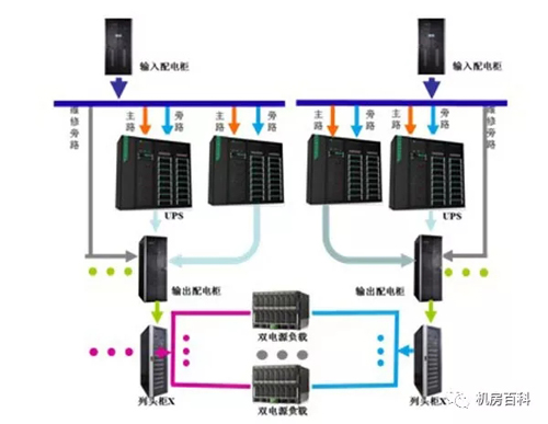
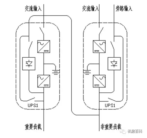
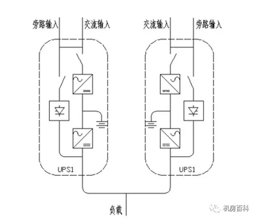
Dual-bus redundant power supply system
The dual-bus power supply configuration employs two independent bus lines to power backend equipment, with each bus equipped with an identical UPS power supply system. This approach eliminates the potential “single-point bottleneck” failure risk that could arise between the UPS output and the end-user load, thereby enhancing the fault-tolerant capability of the power distribution system. This configuration supports online maintenance, online capacity expansion, and online upgrades, improving the availability of critical bus lines and meeting the power requirements of dual-power-supply devices, thus truly achieving 24/7/365 operational reliability. However, the dual-bus redundant power supply scheme effectively entails constructing two complete sets of the aforementioned power supply circuits, which increases costs by more than 100%. Meanwhile, to accommodate single-power-supply equipment, an Static Transfer Switch (STS) can be installed at the output to ensure reliable power delivery.
Installation of power supply and distribution equipment and cable laying
The UPS and precision air-conditioning power systems in the computer room shall be supplied from dedicated incoming distribution panels. These panels shall be fed by two independent power sources with automatic transfer switching. The main power supply and the bypass power supply for the UPS host shall be separately routed, preferably from different incoming distribution panels. The UPS system’s output shall employ a radial, dual-circuit distribution configuration, with three-phase distribution at the point of use and phase separation at the load end to ensure three-phase balance. Distribution panels and UPS power cabinets in the computer room shall be floor-mounted; power distribution boxes and lighting distribution boxes shall be surface-mounted on walls at a height of 1.4 meters above the floor, with concealed installation. The bases of distribution panels and other electrical equipment shall be securely anchored to the building floor and properly grounded. The computer room shall be equipped with separate maintenance and test outlets, clearly distinguished by signage; test outlets shall be powered by the UPS, while maintenance outlets shall be supplied by the mains. All wiring shall be installed in accordance with the equipment layout and design drawings, with particular attention paid to minimizing supply distances. Power, signal, and communication cables within the computer room shall be routed separately and shall not share the same cable tray. Distribution circuits originating from the UPS power distribution panel (cabinet) shall be run in galvanized steel conduit beneath the raised floor, extending to each row of network or server racks, with power supplied to the racks via sockets or industrial connectors.
End-of-Line PDU
As the name suggests, a Power Distribution Unit (PDU) is designed to distribute power and provide additional management functions. Power distribution involves the allocation of current, voltage, and interfaces, while power management encompasses switch control (including remote control), monitoring of various circuit parameters, circuit switching, load limitation, proper matching and installation of power outlets, cable organization, space management, surge protection, and polarity detection. Given that nearly all IT equipment in data centers is already housed—or will soon be housed—in standard server racks, PDUs, as essential rack accessories, are receiving increasing attention from all stakeholders.
Compared with ordinary power strips, PDU power distribution units offer several key advantages: more rational design and layout, stricter quality and compliance standards, longer safe and trouble-free operating life, superior protection against leakage current, overvoltage, and overload, enhanced durability under frequent plugging and unplugging, lower heat generation, and more flexible and convenient installation. They are ideally suited for industrial customers with stringent power requirements and fundamentally eliminate the safety hazards associated with ordinary power strips, such as frequent power outages, equipment damage, and fires caused by poor contact or insufficient load capacity.
Summary
The power supply and distribution system is the most critical infrastructure of a data center and should be comprehensively considered and thoroughly planned from the very outset of data center construction. In accordance with the data center’s requirements for power supply reliability, appropriate technical measures must be implemented in areas such as the selection of power sources, the layout of the power supply and distribution system, and the system’s architecture and configuration. At the same time, proven and effective energy-saving measures should be fully leveraged to minimize losses in the power supply and distribution system. Where a data center comprises functional zones of varying levels of importance, these zones should be treated differently in the design of the power supply and distribution system to reduce unnecessary capital expenditure and operational costs.
Data center,Data Center Power Distribution,Small busbar,Intelligent Busbar
Previous Page
Previous Page
Related News
Exploring the Future Development and Applications of Busbar Trunking Systems
This article explains the importance of busbar trunking systems in modern power systems and their future development trends.
2026-04-10

Hello, how may we assist you?
*Note: Please ensure all information is accurate; we will contact you as soon as possible.
SAF Coolest v1.3.1.1 设置面板 JYOSD-ZUEU-XXZSE-SZV
无数据提示
Sorry, this section is currently being updated. Please stay tuned!
You can view other sections or return.Home