

Data Center Facility Design and Technical Trade-Offs among Various Disciplines
Release Date:
2025-09-15
Data Center Facility Design and Technical Trade-Offs among Various Disciplines
A data center facility is a space that provides the operating environment for electronic information equipment; it may be an entire building or a part of a building, and typically comprises the main computer room, auxiliary areas, support areas, and administrative areas.
1. Introduction to the Data Center Server Room Model
A data center computer room is a facility that provides the operating environment for electronic information equipment; it may be an entire building or a part of a building, and typically comprises a main equipment room, auxiliary areas, support areas, and administrative areas. A typical data center computer room model is shown in Figure 1.
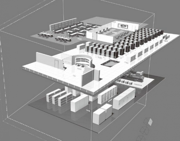 Figure 1
Typical data center server rooms are functionally divided into several key areas, including the auxiliary equipment area (containing UPS systems and batteries, as well as diesel generator sets), the main equipment room, the monitoring room, the conference room, and the office area. In actual construction, the configuration of these functional zones and their layout may vary depending on specific project requirements.
The intended use, management requirements, and critical role of data center facilities in the economy and society underscore their unique characteristics and the imperative of ensuring their security. As a building or a component thereof, such facilities are inevitably subject to external environmental influences that can compromise the normal operation of electronic information equipment within the data center. At best, this results in financial losses; at worst, it may undermine social stability and lead to immeasurable, catastrophic consequences. Key external factors include unauthorized personnel, lightning strikes, flooding, electromagnetic interference, and seismic activity. Typical risk identification and control measures for data center facilities are illustrated in Figure 2.
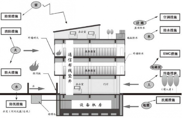 Figure 2
Given the unique characteristics of data centers and the need for risk control, the scope of work typically encompassed in a standard data center facility project primarily includes the following aspects.
(1) Decoration and renovation works
① Data center environmental engineering;
② Office area environmental engineering;
③ Environmental engineering in the monitoring area;
④ Environmental Engineering in the Power Zone.
(2) Electrical Engineering
① Diesel generator system;
② Uninterruptible Power Supply Distribution System;
③ Power distribution system;
④ Lighting distribution system;
⑤ Power surge protection system;
⑥ Data center grounding system.
(3) Air-Conditioning Engineering
① Dedicated air-conditioning system;
② Auxiliary air conditioning system;
③ New exhaust ventilation system project.
(4) Fire Protection Engineering
① Automatic alarm system;
② Zoned gaseous fire suppression system;
③ Zoned water spray system.
(5) Low-Voltage Engineering
① Building automation system;
② Security Control and Management System;
③ Communication network automation management system;
④ Structured cabling system;
⑤ Public information system;
⑥ Monitoring Center Control System.
The typical professional distribution of a data center server room is shown in Figure 3.
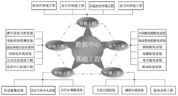 Figure 3
The intended purpose of data center facility projects dictates the complexity of their design and construction. During the design and construction phases, particular emphasis should be placed on addressing the following key issues: availability, manageability, security and reliability, as well as energy efficiency and environmental sustainability.
To better address the aforementioned issues, all parties involved in the design and construction of data center facilities should comprehensively consider the technical requirements of each discipline, effectively integrate, coordinate, and consolidate these disciplines, ensure that each discipline performs its intended function within the data center, and thereby create an efficient, cohesive system that provides a high-performance, stable operating environment for the electronic information equipment housed therein.
Data center facility engineering design and construction involve a wide range of issues. This paper discusses several cross-disciplinary challenges and, drawing on the author’s many years of project experience, proposes corresponding solutions: airflow management in hot and cold aisles; integrated utility pipeline coordination; and a centralized monitoring platform.
2 Airflow Organization in Hot and Cold Corridors
The airflow configuration in the data center computer room shall be determined based on the cooling method of the electronic information equipment, the equipment layout and density, the equipment heat dissipation rate and heat dissipation mode, the indoor air velocity, dust-control requirements, noise considerations, and other relevant factors, while also taking into account the building’s architectural constraints. The airflow configuration, air outlet types, and supply–return air temperature difference are shown in Table 1.
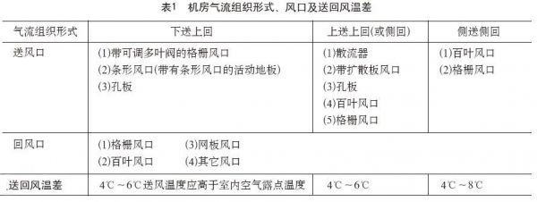 Table 1
In data center server room projects, when cabinet or rack heights exceed 1.8 meters, or when equipment has high thermal density, generates substantial heat, or imposes a heavy thermal load, underfloor air distribution with overhead return is typically employed. Currently, the most widely used and most suitable airflow configuration is the hot–cold aisle containment system, in which cold air is supplied from the front of the cabinets or racks and warm air is exhausted from the rear. With equipment installed inside the cabinets or racks, excellent cooling performance can be achieved, as illustrated in Figure 4.
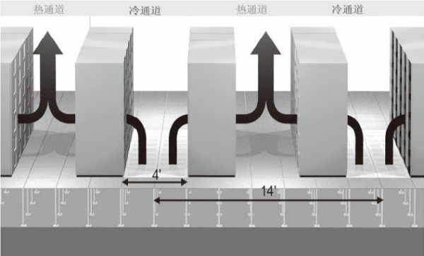 Figure 4
In accordance with the aforementioned airflow organization requirements, the following issues should be effectively addressed:
(1) Formation of the Static Pressure Box
According to the requirements of the “Design Code for Electronic Information System Computer Rooms GB 50174-2008,” when the space beneath the raised floor is used as a plenum, the floor height shall not be less than 400 mm. When the space beneath the raised floor serves as a plenum, the following measures shall also be implemented:
① High-quality raised access flooring should be selected whenever possible to ensure that the materials do not deform or expand under long-term low-temperature, constant-humidity conditions.
② The installation of the raised access floor shall be subject to enhanced quality management, with particular emphasis on ensuring secure fixing at edges and corners to prevent deformation that could compromise the airtightness of the plenum.
③ The space beneath the raised floor shall be properly sealed, particularly at locations such as cable and conduit penetrations, doorways (openings), and lightweight partitions, to ensure the airtightness of the plenum.
④ The area beneath the cabinet or other electronic information equipment, as well as the cable entry points below, shall be sealed.
(2) Thermal Insulation Treatment
Currently, most data center server rooms employ dedicated precision air-conditioning systems. To maintain the server room temperature at 23°C ± 1°C, the supply-air temperature from the air-conditioning units—whether water-cooled or air-cooled—is typically kept below 15°C. Consequently, the air temperature within the entire static-pressure plenum also remains at this level. Meanwhile, the lower-level office area generally maintains a room temperature of around 25°C. This results in a temperature difference of nearly 10°C between the upper and lower levels of the server room, making condensation on the lower-floor slab highly likely and potentially compromising the usability of the lower-level office space. Therefore, effective thermal insulation beneath the floor is essential. The selected insulation material must comply with fire-safety regulations and be environmentally friendly. At present, closed-cell rubber-plastic boards are commonly used for underfloor insulation.
(3) Equipment Layout
To ensure smooth airflow distribution, the layout of equipment within the data center server room should facilitate efficient supply and return air from the HVAC system. A widely adopted practice is to align equipment racks parallel to the airflow direction of the HVAC units, thereby avoiding cross-flow or even vertical airflow. In the typical data center server room model shown in Figure 1, the front face of the HVAC unit should be perpendicular to the front and rear faces of the equipment racks (or cabinets).
The front doors of cabinets or racks should face the cold aisle, while the rear doors should face the hot aisle. Since the fans on most electronic information equipment are mounted on the rear side, this arrangement facilitates the active circulation of cool air from the cold aisle through the equipment, significantly enhancing heat dissipation.
Different types of electronic information equipment may be installed in various data center server rooms; however, regardless of the specific equipment type, the layout should, whenever possible, adhere to the principles outlined above when implementing a hot–cold aisle airflow configuration.
(4) Floor Layout and Air Outlet Installation
When data center server rooms employ a hot–cold aisle containment airflow configuration, raised access floors are typically used. Currently, anti-static raised access floors measuring 600 × 600 mm are widely adopted in such projects. When selecting perforated floor panels, preference should be given to those that are specifically matched to the corresponding flooring system. In accordance with the airflow management requirements for hot–cold aisle configurations, perforated floor panels should be installed in the cold aisles, while the areas beneath cabinets and other IT equipment should be sealed. Following this principle, and to facilitate subsequent operation and maintenance as well as maintain a clean and aesthetically pleasing environment, it is recommended to use full-width perforated floor panels in the cold aisles (along the equipment rows). Taking floor panel dimensions into account, if two rows of perforated floor panels (each measuring 600 × 600 mm) are installed in the cold aisle, the aisle width should be no less than 1,200 mm—enough to accommodate two full-length perforated panels. Considering the dimensions of equipment and cabinets, the width of the hot aisle may be adjusted accordingly to ensure proper alignment between the equipment/cabinets and the floor joints.
During the design of a data center computer room, the design team shall specify the number and locations of raised-floor air outlets on the floor plan. The number and installation positions of these outlets shall be determined through comprehensive consideration of factors such as equipment heat dissipation, the ventilation rate of the raised-floor air outlets, and indoor temperature differential control, and shall be calculated and designed by HVAC specialists. During the commissioning phase at the project’s later stage, the commissioning personnel may make appropriate adjustments to the number and installation positions of the raised-floor air outlets based on test data; however, such adjustments must be approved by the design firm.
(5) Pipeline Integration
Data center equipment room pipeline integration is a complex yet essential task; specific solutions are detailed below. In data center projects that employ hot-cold aisle airflow containment, pipeline integration should be carried out in accordance with the principle of facilitating smooth airflow.
(6) Return Air Assurance Measures
As shown in Figure 4, the hot air in the hot aisle should flow smoothly back to the air-conditioning unit for cooling treatment, thereby effectively ensuring smooth airflow organization and reducing equipment temperatures. The main measures to ensure proper return air include:
As shown in Figure 4, sufficient clearance above cabinets or equipment must be provided to effectively meet return-air requirements. Based on engineering experience, the height of cabinets or equipment generally does not exceed 2 m, and the clear vertical space above them should be no less than 0.6 m. Consequently, the effective clear ceiling height in the equipment room should be maintained at 2.6 m or more; this requirement is even more critical for data centers employing overhead cabling, where the clear height must also be no less than 2.6 m. When selecting the site for the equipment room, the building’s floor-to-floor height should be carefully considered to ensure that the required clear height is met.
In the overhead cable tray room, comprehensive pipeline layout should fully take into account the principle of facilitating return air.
The return air inlet of the air conditioning unit shall ensure unobstructed return airflow and shall not be blocked.
(7) Dust-proof treatment
According to data center room requirements, testing shall be conducted under static conditions, with the number of dust particles ≥0.5 μm in the room not exceeding 18,000 particles per liter. In data center rooms that employ a hot-cold aisle containment airflow configuration, air flow is highly unobstructed. This necessitates thorough dust-control measures within the airflow containment channels.
The existing subfloor shall be properly treated for dust control. Prior to installing floor insulation and the flooring system, the subfloor must be thoroughly cleaned and coated (or sprayed) with a dust-proof coating, with corresponding concealed inspection records maintained.
The existing floor slab (or the effective transfer layer) shall be properly treated for dust prevention. Prior to the construction of the suspended ceiling or the transfer layer, the existing floor slab (or the effective transfer layer) shall be thoroughly cleaned and coated (or sprayed) with a dust-proof coating, and concealed inspection records shall be maintained.
In data center server rooms, the use of dust-prone insulation materials such as glass wool for ductwork and other components should be minimized.
(8) Environmental Protection and Energy-Saving Measures
The latest data center facility engineering standards emphasize green and sustainable development, making the design and construction of green data center facilities a shared long-term goal for all stakeholders.
Green data center projects involve numerous disciplines and highly complex technical content. Drawing on practical engineering experience, the author hereby outlines the key considerations for environmental protection and energy efficiency in server room designs that employ hot-cold aisle containment airflow management:
As mentioned earlier, to ensure effective return air, the clear height of the equipment room should not be less than 2.6 meters. However, a higher ceiling is not always better. An excessively high clear height increases the space available for airflow distribution, thereby increasing the cooling load on the air-conditioning system and undermining energy efficiency. A clear height between 2.6 and 3.0 meters strikes an optimal balance between adequate return-air performance and energy savings. Therefore, this factor should be carefully considered when selecting the site for the equipment room. If the floor-to-ceiling height is too great, it is generally recommended to install a secondary suspended ceiling and a transition floor to reduce the effective clear height.
To ensure unobstructed airflow, the data center’s air-conditioning units will deliver pressurized supply air. The distance from the air-conditioning unit’s outlet to the farthest floor-mounted diffuser is commonly referred to as the supply-air delivery distance. When this distance is excessive, the supply-air pressure must be higher; however, higher pressure leads to increased noise levels in the data center and significantly reduces the efficiency of the air-conditioning system. In manned main computer rooms and auxiliary areas, when electronic information equipment is shut down, the noise level measured at the main operator’s station shall be less than 65 dB(A). To minimize data-center noise and enhance air-conditioning efficiency, the supply-air delivery distance should not exceed 15 meters. These considerations should be incorporated during site selection, design, and layout planning for the data center.
3 Pipeline Comprehensive Coordination
Data center server rooms are integrated projects that involve multiple disciplines. To effectively address key challenges such as interdisciplinary coordination, environmental protection and energy efficiency, ease of use, scalability, and aesthetic appeal, comprehensive utility pipeline integration is both essential and highly complex. Prior to and throughout the design and construction phases, all stakeholders—including designers and contractors—should develop and implement a well-coordinated plan tailored to the specific requirements of the project.
Currently, an increasing number of data center projects are adopting a top-cable-routing, drop-ceiling-free approach for integrated utility routing. In this paper, the author provides an overview of integrated utility routing in such typical data center server rooms.
(1) Installation of the top combined support
In data center server rooms that employ overhead cabling, extensive mechanical and electrical installation work is carried out on the ceiling, including lighting fixtures, power and low-voltage cable trays, ductwork, fire alarm systems, gaseous fire suppression piping, and surveillance cameras. Under conventional installation practices, construction personnel drill numerous holes in the existing ceiling slab and secure components using expansion bolts. This installation method gives rise to the following adverse effects:
① Drilling numerous holes in the original roof slab will compromise the structural integrity of the existing floor slab;
② Once installed, the equipment must not be relocated, as this would hinder the subsequent installation and operation of electronic information equipment.
③ Poor scalability. As the data center evolves over time, the number of devices within the facility is likely to increase, necessitating additional cable trays for both power and low-voltage cabling. If traditional installation methods are used, this will inevitably require re-drilling holes during later installations, making it challenging to protect finished surfaces.
The top-mounted composite support system effectively addresses the aforementioned adverse effects. The so-called top-mounted composite support refers to the installation of a 1200 mm × 1200 mm grid-shaped, ∏-section steel transfer layer beneath the original floor slab. All installation work is carried out on this transfer layer and the equipment is securely clipped onto it rather than being welded. As a result, the installed equipment can slide along the transfer layer, thereby enhancing the flexibility and scalability of the equipment room. For lighting fixtures, a reverse ∏-section main runner is used, with the corresponding power cables routed inside the runner; the fixtures can also be slid along the runner as needed. Figure 5 shows an example of the top-mounted composite support installation.
Figure 5
(2) Arrangement and installation of the top-level gas fire suppression piping and alarm piping
In the equipment room with no suspended ceiling at the top, only a single layer of gaseous fire suppression piping and alarm system shall be installed on the ceiling. The fire alarm shall be mounted at the highest point of the ceiling, while the gaseous fire suppression piping shall be installed directly adjacent to the transition floor.
(3) Layout and installation of the new exhaust duct at the top
To ensure adequate clear height and smooth airflow within the equipment room, new exhaust ductwork should, subject to compliance with relevant codes and standards, be installed as close as possible to the ceiling along the room’s walls; however, it must not be mounted directly in front of or directly above the air-conditioning units to avoid obstructing the return air. In addition, ductwork routing should align with the supply and return airflow directions of the air-conditioning system and should avoid crossings or, even more so, vertical intersections.
(4) Lighting Fixture Layout and Installation
In equipment rooms without a suspended ceiling, luminaires should be installed above the equipment or equipment rack rows, rather than directly above individual pieces of equipment or racks. This arrangement ensures that operators can make effective use of the lighting during operations. The mounting height of the luminaires should be positioned between the fire protection systems (gas suppression and alarm systems) and the power and low-voltage cable trays.
(5) Layout and installation of overhead cable trays for power and low-voltage circuits
In data centers that employ top cable routing, the installation of power and low-voltage cable trays should be coordinated with the equipment’s cable exit configuration. For example, if certain cabinets or devices have their cables exiting from the rear, the corresponding cable trays should be installed along the rear wall; conversely, if cables exit from the front, the trays should be installed along the front wall. In addition, to ensure that the bending radius of cables as they exit the trays complies with relevant standards and that the cable runs are straight and aesthetically pleasing, the tray height should ideally be 200–400 mm above the cabinet, while the clearance from the finished floor should not be less than 2.2 m. Furthermore, within the data center, cable trays of the same type should be kept as uniform in height as possible.
During the installation of power and low-voltage cable trays, they shall be aligned with the airflow direction of the air-conditioning return vents; crossing or, even more so, vertical intersection should be avoided, particularly in the vicinity of the air-conditioning unit’s return air inlet.
(6) Layout and installation of underfloor gas fire suppression piping and alarm wiring
Underfloor gas fire-extinguishing piping and alarm wiring should be installed as close as possible to the underside of the raised floor, aligned with the direction of the air-conditioning supply airflow, and avoid crossing or even running perpendicular to it; in particular, crossings or vertical runs near the air-conditioning unit’s supply air outlets should be strictly avoided.
(7) Layout and Installation of Underfloor Cable Trays
Currently, most equipment rooms without suspended ceilings adopt a wiring configuration in which low-voltage cables are routed overhead and high-voltage cables are routed beneath the floor. When installing high-voltage cable trays under the floor, they should be aligned with the air-supply direction of the HVAC system; crossing or, even more so, running perpendicular to the airflow is undesirable, particularly near the air supply outlets of the HVAC units.
To ensure smooth airflow, cable trays shall be installed beneath the raised floor in the hot aisle.
It should be specifically noted that, during the installation of the air-conditioning unit’s power cables, the cable tray must be mounted on the rear side of the unit to avoid obstructing the unit’s airflow.
Related News
Exploring the Future Development and Applications of Busbar Trunking Systems
This article explains the importance of busbar trunking systems in modern power systems and their future development trends.
2026-04-10

Hello, how may we assist you?
*Note: Please ensure all information is accurate; we will contact you as soon as possible.
SAF Coolest v1.3.1.1 设置面板 JYOSD-ZUEU-XXZSE-SZV
无数据提示
Sorry, this section is currently being updated. Please stay tuned!
You can view other sections or return.Home